实验目的:
1、掌握HDLC基本配置。
2、理解HDLC封装格式。
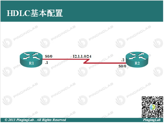
实验拓扑:

实验步骤:
1、依据图中拓扑,为R1和R2的串口链路部署HDLC封装和IP地址,配置如下:
R1上
R1(config)#int s0/0

R1(config-if)#no shutdown

R1(config-if)#encapsulation hdlc

R1(config-if)#ip address 12.1.1.1 255.255.255.0

R1(config-if)#exit
R2上
R2(config)#int s0/0

R2(config-if)#no shutdown

R2(config-if)#encapsulation hdlc

R2(config-if)#ip address 12.1.1.2 255.255.255.0

R2(config-if)#exit
2、查看接口封装情况,并测试直连连通性。
R1#show interfaces s0/0

Serial0/0 is up, line protocol is up

  Hardware is M4T

  Internet address is 12.1.1.1/24

  MTU 1500 bytes, BW 1544 Kbit, DLY 20000 usec,

     reliability 255/255, txload 1/255, rxload 1/255

  Encapsulation HDLC, crc 16, loopback not set

  Keepalive set (10 sec)

  Restart-Delay is 0 secs

  Last input 00:00:01, output 00:00:09, output hang never

  Last clearing of "show interface" counters never

  Input queue: 0/75/0/0 (size/max/drops/flushes); Total output drops: 0

  Queueing strategy: weighted fair

  Output queue: 0/1000/64/0 (size/max total/threshold/drops)

     Conversations  0/1/256 (active/max active/max total)

     Reserved Conversations 0/0 (allocated/max allocated)

     Available Bandwidth 1158 kilobits/sec

  5 minute input rate 0 bits/sec, 0 packets/sec

  5 minute output rate 0 bits/sec, 0 packets/sec

     24 packets input, 2262 bytes, 0 no buffer

     Received 24 broadcasts, 0 runts, 0 giants, 0 throttles

     0 input errors, 0 CRC, 0 frame, 0 overrun, 0 ignored, 0 abort

     31 packets output, 2982 bytes, 0 underruns

     0 output errors, 0 collisions, 3 interface resets

     0 output buffer failures, 0 output buffers swapped out

     4 carrier transitions     DCD=up  DSR=up  DTR=up  RTS=up  CTS=up
可以看到,路由器采用HDLC协议进行封装,并且接口处于正常状态,在R1上Ping R2,如下:
R1#ping 12.1.1.2


Type escape sequence to abort.

Sending 5, 100-byte ICMP Echos to 12.1.1.2, timeout is 2 seconds:

!!!!!

Success rate is 100 percent (5/5), round-trip min/avg/max = 20/25/40 ms
此时,通过HDLC封装后,直连连通性正常。
3、查看HDLC封装格式,如下:

可以看到,此处的二层封装协议为Cisco HDLC而不是官方的HDLC,Cisco路由器默认采用便是私有的HDLC封装,与其他厂商不兼容,若广域网链路有其他厂商的设备,则需要采用PPP协议进行封装。此实验完成。
- 还没有人评论,欢迎说说您的想法!
